‘Dye-ing’ to Begin My Build

For several months, not much progress has happened on the TVT.  An attention-challenged collector, I’m always being tempted by other things.  I ended up making a few more acquisitions in the last few months, including a second SWTPC 6800 system, a Netronics video terminal (and homebrew Z80 computer), a Jupiter Ace.. oh, and did I mention I scored some original Mark-8 boards?  🙂 I also got wind of another possible project – building a replica of the original SOL Terminal prototype.  I actually discovered I had the proper keyboard to do it!   But I digress.

Part of my problem with getting going on the TVT was knowing where to start.  My logical brain said: go with the mainboard.  But I didn’t have the transformers, nor some other odds and ends, and I kept delaying.  Eventually I realized time was passing quickly, and maybe I could just build what I could and get going, and then fill in the blanks later?

So that’s what I decided to do!  I decided I’d not care what order I went, I’d just make sure I was building the TVT every day I could, a bit at a time.  Whatever I could do, I would do.  That’s the only way to get there.  Otherwise, procrastination leads to a dead project.

One detour before I built though, I decided I wasn’t quite satisfied with the colour of my boards.  They just don’t look vintage enough in my eyes, up close.  The old process of making PCB substrate (the fibreglass/plastic the copper traces are attached to) produced something that was somewhat fluorescent.  That process was problematic and is no longer in use.  Today’s boards tend to be either brown, or yellow, or a very light yellow green.  I chose the latter since that was as close as I could get to the kind of vintage green you see on originals.  Even now, I’m still not wild about it.  I’ve had some crazy thoughts, like getting a piece of original substrate and having it replated with copper and then I could etch it.  But, finding original substrate is almost impossible and the cost to do all that would be exorbitant.  How about dyeing?

Yes, apparently you can dye PCBs.  It’s simple.  You get some Rit fabric dye, a pot your spouse won’t mind you destroying, and throw it in some hot water and boil your PCB until it attains the color you desire.

I decided, looking at my boards, they weren’t green enough.  They were more on the yellow side, so, drawing on my experiences as an art student in the ancient past, thought I’d try using blue dye to green it more.  Royal Blue, to be exact.

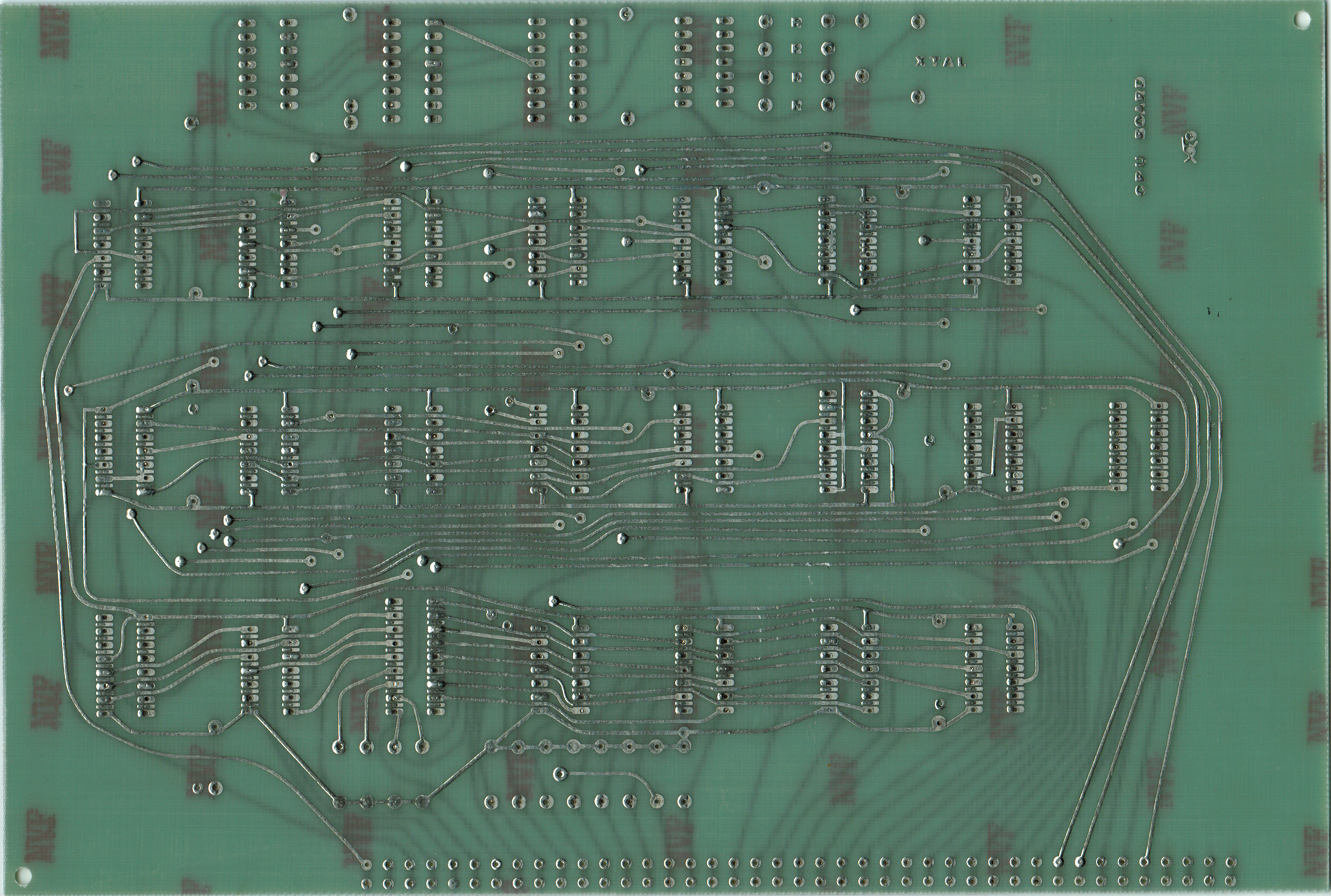
First, a comparison of colour.  On the left, my new TVT mainboard.  On the right, an original Mark-8 CPU board.  You can see the difference right away — the bright fluorescent hue.  This is likely impossible to reproduce with dye, but let’s see how close we can get.

The instructions say you mix up the dye separately in a cup or so of hot water, and then add to your hot pot.  I guess this is to prevent clumping of the dye powder.

Next you need to build an apparatus to allow the board to be suspended in the pot.  I don’t have any photos of my mainboard being dipped, but I do have photos of a Mark-8 reproduction board I was working on simultaneously:

I had the oven on high for about an hour.  I didn’t notice any difference on inspection.  I then left it simmering, for an hour, then two, then turned it off and left it overnight.  I still wasn’t noticing a difference, so I decided to add more dye.  Within an hour, there was a striking difference.  Here’s two of my repro Mark-8 boards side by side just to give you an idea.  One is undyed.

Quite a difference with the dye, huh?  And here’s a comparison shot of the dyed Mark-8 board against that same board and an original SWTPC GT-6144 graphics board:

Unfortunately, not the correct color for the Mark-8 boards produced by Techniques, but could be legit as a totally home brew.  And close to SWTPC, which provided the original TVT boards in the kit Radio Electronics offered.

I dyed my TVT boards with this stronger batch of dye.  I ‘blue’ it!

Oops.

Definitely a little heavy on the blue.  I can live with it, but a note for next time: keep the amount of dye relative to water light.  My SWTPC boards went into the dye after I had doubled the blue, and so consequently the blue sunk in much more quickly.  Further, the manufacturer of the boards I used for my TVT is a different one than my Mark-8.  Subtle differences in the substrate result in different colors.  That said, some of the boards I put in after the mainboard benefitted from that lesson, and actually came out pretty close to original colour.  Check out the Timing board here vs. an original P197 SWTPC power supply board:

I mean, that’s kind of as close as I think you’re going to get with new substrate.  Gotta be happy with that.

Lesson learned: more dye = less soaking time, less dye = more.

On to the build!

Preparing and etching the Mark-8 CPU clone board

Okay so on my last post I had tweaked artwork and set up for trying to make a copy of my Mark-8 CPU board.  I got my double-sided copper clad in yesterday and am raring to go!

In terms of process, it’s very similar to what I went through with my TVT boards.  The difference this time is I have an original for reference and can be a bit more confident that my work is good.

The first thing was to print out the artwork on my favourite Hot Rod Magazine paper.  I don’t know why but this stuff transfers really well.

The challenge with doing a double-sided board is getting both sides to align just-so so that your ICs and components will install easily.  This is why I went to some lengths to make sure the artwork matched properly in Photoshop.  Now I had to align it on the copper clad.

The strategy I settled on was to drill holes in a couple of IC and resistor pads up top and below.  I reasoned that these were so small that if they aligned okay, I knew I’d be good.  I then made holes in the appropriate places on the artwork.  I used a small piece of wire to go through the PCB and transfer paper and bent on one side to secure.  I did this in three locations just to be safe.  In the first photo you can see the little pin through on the other side.

Basically from there it was just carefully aligning the transfer sheet for side two to those pins, and once the pins were through bending them to hold it in place.  Then I took some scotch tape and pressed it down on the corners to hold.  I didn’t want the pins staying in and damaging the iron or ripping the paper, obviously as I ironed.

Ironing went fairly smoothly, however I did note that the resulting heat caused the opposite side I was ironing to actually smudge the toner in a couple of places.  Hrmm.  Not sure how to get around that.  Perhaps having the ironing happening on something cool?  The counter top does get pretty hot when I’m doing this.

When I dipped the boards into the cooling bath and removed the paper, I discovered, as usual, the iron had missed in a few places.  Almost always does.  So I did touching up with nail polish to fill gaps.

Anyway, once that was done, I used my original board (very carefully) as a guide to trace cutting lines so I could cut the board to be the exact same size.  Voila, side by side:

Next was etching.  I’m still wussing out from using heavier stuff like my ferric chloride.  I think I might be getting over that.  One problem with using the friendlier vinegar/peroxide/salt etchant is that it takes a ton of it to etch boards this big.   I used 6 500ml bottles of peroxide and an equivalent amount of household cleaning vinegar.  It took something like 2 hours to etch off the acres of copper on this board that needed to go.  And unfortunately that’s too long for the nail polish ‘patches’ to hang on.  The nail polish eventually lets go and that copper becomes exposed.  I had to apply it again to try and save those traces, but a few were eaten right though.

Overall the result after etching isn’t too bad.  Side 2 came out really nice and clean.  I think I have to do more work on Side 1’s artwork to make the traces a bit darker and a tiny bit thicker.

Lastly I took some acetone and wiped away the toner.  Then I drilled out some of the pads to test how both sides aligned.  I’m delighted to say the alignment is just a hair off in a few places.  But otherwise, it’s darn near perfect, especially considering the bozo (me) trying to align them.

So there you have it.  I’m going to use this board as an experiment piece.  I want to see if dying it with some blue or green Rit dye gets me a bit closer to the color of the original (right).  Then I’ll learn about tinning, and just see how close I can dial it in.

To recap: I need to figure out how to better transfer toner.  I’ve stuck with ironing because it has served me well.  My laminator did not do a good job and these fancy transfer papers seem to be even less reliable than my magazine paper.  I also need to maybe adopt a better etching process.  But for a first try, I’m pretty happy.  This gives me confidence that the end goal is attainable.

Mark-8 Clone Project Begins

Christmas is done (yay!) and now I have a bit of free time before we go back to work for vintage computer projects.  And what better way to close out the old year and ring in a new one by attempting to clone Jon Titus’ Mark-8 boards?

In earlier posts I detailed my adventures in recreating the board set for Don Lancaster’s TV Typewriter.  That project is still ongoing, but by far the most fun I had was taking scans of the original artwork and then transferring that onto copper, and I’ve been looking for excuses to make new PCBs for something else.

Recently I acquired some original, untouched Mark-8 boards on Ebay.  That remains the pinnacle of my collecting career, given how rare these are.  However I bought them without really thinking through what it meant.  Boards alone do not a computer make, and to take a soldering iron to these means risking damage, both literal and in terms of value.  There are only around 20 or so Mark-8s known to exist, and of those, only mine and one other set are known to be unbuilt.

I’m not totally against building them though.  I solicited opinions all over the place and many were of the mindset that a computer is pointless if it doesn’t do anything.

It’s a tough one.  But in the interim, there’s no crime against history in recreating some new boards.  At the very least, I can use them as practice runs for potentially building these ones one day.  Better to learn on something that isn’t virtually irreplaceable first.  I’m therefore setting a goal of recreating new boards that look as close to the originals as possible.  I’ve even read up on how to dye my new PCB stock to more closely match the color of the original, and even how to create a stamp to mark the boards with the similar marks the PCB fab house would have used.

To be clear, cloning the Mark-8 boards has been possible all the way back to day one.  The original construction guide provided the artwork to make your own.  In fact,  Steve Gabaly (aka Obtronix) took copies of said artwork and produced a kit, which some unethical types occasionally tried to pass off as original on Ebay.  I’m told these kits had some issues, owing to the quality of the copied artwork they were based on.

I had actually planned to go the same route myself using a PDF of the construction kit Bryan the ‘Byte Collector’ was kind enough to scan and put on his site.  That had been my original ‘get a Mark-8’ plan going back years.  I “knew” the odds of affording, let alone seeing a Mark-8 for sale anywhere were slim to none.

I was warned though not to trust the construction guide copies found online.  Copying and scanning does funny things to artwork.  I ran into this on my TVT build:  the artwork had to be scaled up slightly to fit components properly.  Lacking an original TVT to compare to, I’m still not sure I’m 100% in the zone, but checking against ICs and components, they look right.

An additional challenge: Mark-8 boards, unlike the TVT, are double-sided.  I’ve never made double-sided boards before.  I’m lucky the originals weren’t (for cost reasons) through plate – I’d never be able to do that myself, so at least mine can still be in keeping with the originals that way.  But I know lining up two distinct pieces of artwork and making it come together just so will be a huge challenge for someone of my limited skills.

However, I do have the advantage of having the original boards to compare against.  Further, a Mark-8 clone would be the perfect companion to my TVT clone – both were signature Radio Electronics magazine projects, and in fact the Mark-8 information mentioned the TVT as a possible interface device.

Now, originally I was just going to import the scanned artwork into Photoshop and then keep tweaking the size and printing it until the IC pads fit the ICs, which I have.  But since I have the originals, I have an advantage others didn’t.  So what I’ll do is actually scan the originals on my scanner.  That’ll give me something visual onscreen to compare to.

The first thing I did was put it (gently) on my scanner.  I didn’t need anything high-res here, just good enough to clearly see the traces.  The result (of the first side):

A direct scan of my original Mark-8 CPU board.

Pretty elegant, huh?

After converting the artwork in the PDF to JPG, I then imported the first side of the CPU board artwork into Photoshop.  Next, I opened up the scan I made of the original in a separate window.  I realized I had to do a bit of scaling to get the artwork into roughly the same size as the original. So I went back to the artwork, rescaled it, and then used the marquee tool to highlight and copy all of it.  Now I brought it over into the other window and pasted it as a second layer.  This of course completely obscures the original board below, however by changing the opacity of the new layer (called Layer 2) over on the right side of the screen, I can make it so that I can see through the artwork I’ve pasted to the original below.  This will help me align the two and do any changes necessary to make them as close as possible.

Okay so obviously I needed to further reduce the size of the artwork, which I did.  However, reducing wasn’t enough.  Looking at the two interspersed with each other it became really apparent just how skewed the scanned artwork was.  It wasn’t, like the TVT, just a matter of being the wrong size.  It was actually distorted in a sort of trapezoidal shape.  Thank goodness I had the originals to rely on.  If I’d tried to make a go of it with these, I’dve been hopelessly lost!

Anyway, since I have the original to use as a guide, I’d just have to make use of the appropriately named Distortion tool, and Skew tool, to fix the messed up artwork.   After half an hour of carpal tunnel-inducing fine mousework, I had them more or less aligned.  The screenshot below shows me about 90% of the way there:

After getting it the rest of the way, returned the opacity to 100%, did the marquee tool and copied the now-corrected artwork back over to the original window.  After clearing that window and pasting it there, I then flipped it horizontally (since I intend to use the toner transfer method again this is necessary to prevent it from producing a mirror image when applied to the copper clad board), whitened up the background and saved it.  Then I printed it off and using a bright light behind compared it to the original board.  It aligned almost perfectly!

Having completed that side, I turned my attention to the other side of the CPU board.  I followed the same process, scanning the backside of the original, importing the artwork and so on.  The back side was even worse than the front.  It was way off, and I really had to work that distortion tool to get it correct against the original.

After completing and saving it, I decided to check not only how it compared to the original but how it lined up with the first side artwork I had fixed.   To my surprise, it didn’t quite line up right.  In fact, some of the bus holes were as much as several mm off!

Hmmm.. how to fix that.  Aha!  I’ll use the two sides of the corrected artwork and align them against each other.  I figured the easiest way to achieve this was to invert one side (making the black and white colors reverse), and then copy the other side over it, and set opacity down to 50% on the copied layer.

Then it was just a matter of making the black traces of the copied layer line up with the white ‘spaces’ of the inverted layer.

It took a bit more finagling, some rotation and so forth before I had it pretty much dead on.  Once that was done, I again brought the opacity of my Side 1 layer back to 100% and then copied over to a new, clean window.  I reversed the inversion on Side 2 and saved both.

Now I have nice , fairly correct artwork for the first board:

Yes, I did make one tiny alteration.  The construction article artwork doesn’t have the manufacturer’s (Techniques) mark right beside where it says ‘CPU BOARD’.  I actually copied that from my originals, converted to black and white and touched it up and then pasted it to my artwork.

The print copies of the artwork line up nicely when put together:

And they look pretty good dimensionally next to the original board:

The artwork is nice and dark and should transfer pretty nicely.  I can’t wait for my double-sided PCB stock to arrive so I can try it out!