Christmas is done (yay!) and now I have a bit of free time before we go back to work for vintage computer projects. And what better way to close out the old year and ring in a new one by attempting to clone Jon Titus’ Mark-8 boards?
In earlier posts I detailed my adventures in recreating the board set for Don Lancaster’s TV Typewriter. That project is still ongoing, but by far the most fun I had was taking scans of the original artwork and then transferring that onto copper, and I’ve been looking for excuses to make new PCBs for something else.
Recently I acquired some original, untouched Mark-8 boards on Ebay. That remains the pinnacle of my collecting career, given how rare these are. However I bought them without really thinking through what it meant. Boards alone do not a computer make, and to take a soldering iron to these means risking damage, both literal and in terms of value. There are only around 20 or so Mark-8s known to exist, and of those, only mine and one other set are known to be unbuilt.
I’m not totally against building them though. I solicited opinions all over the place and many were of the mindset that a computer is pointless if it doesn’t do anything.
It’s a tough one. But in the interim, there’s no crime against history in recreating some new boards. At the very least, I can use them as practice runs for potentially building these ones one day. Better to learn on something that isn’t virtually irreplaceable first. I’m therefore setting a goal of recreating new boards that look as close to the originals as possible. I’ve even read up on how to dye my new PCB stock to more closely match the color of the original, and even how to create a stamp to mark the boards with the similar marks the PCB fab house would have used.
To be clear, cloning the Mark-8 boards has been possible all the way back to day one. The original construction guide provided the artwork to make your own. In fact, Steve Gabaly (aka Obtronix) took copies of said artwork and produced a kit, which some unethical types occasionally tried to pass off as original on Ebay. I’m told these kits had some issues, owing to the quality of the copied artwork they were based on.
I had actually planned to go the same route myself using a PDF of the construction kit Bryan the ‘Byte Collector’ was kind enough to scan and put on his site. That had been my original ‘get a Mark-8’ plan going back years. I “knew” the odds of affording, let alone seeing a Mark-8 for sale anywhere were slim to none.
I was warned though not to trust the construction guide copies found online. Copying and scanning does funny things to artwork. I ran into this on my TVT build: the artwork had to be scaled up slightly to fit components properly. Lacking an original TVT to compare to, I’m still not sure I’m 100% in the zone, but checking against ICs and components, they look right.
An additional challenge: Mark-8 boards, unlike the TVT, are double-sided. I’ve never made double-sided boards before. I’m lucky the originals weren’t (for cost reasons) through plate – I’d never be able to do that myself, so at least mine can still be in keeping with the originals that way. But I know lining up two distinct pieces of artwork and making it come together just so will be a huge challenge for someone of my limited skills.
However, I do have the advantage of having the original boards to compare against. Further, a Mark-8 clone would be the perfect companion to my TVT clone – both were signature Radio Electronics magazine projects, and in fact the Mark-8 information mentioned the TVT as a possible interface device.
Now, originally I was just going to import the scanned artwork into Photoshop and then keep tweaking the size and printing it until the IC pads fit the ICs, which I have. But since I have the originals, I have an advantage others didn’t. So what I’ll do is actually scan the originals on my scanner. That’ll give me something visual onscreen to compare to.
The first thing I did was put it (gently) on my scanner. I didn’t need anything high-res here, just good enough to clearly see the traces. The result (of the first side):
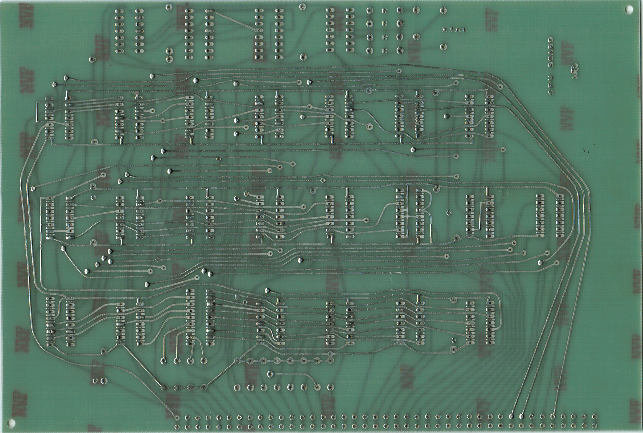
Pretty elegant, huh?
After converting the artwork in the PDF to JPG, I then imported the first side of the CPU board artwork into Photoshop. Next, I opened up the scan I made of the original in a separate window. I realized I had to do a bit of scaling to get the artwork into roughly the same size as the original. So I went back to the artwork, rescaled it, and then used the marquee tool to highlight and copy all of it. Now I brought it over into the other window and pasted it as a second layer. This of course completely obscures the original board below, however by changing the opacity of the new layer (called Layer 2) over on the right side of the screen, I can make it so that I can see through the artwork I’ve pasted to the original below. This will help me align the two and do any changes necessary to make them as close as possible.

Okay so obviously I needed to further reduce the size of the artwork, which I did. However, reducing wasn’t enough. Looking at the two interspersed with each other it became really apparent just how skewed the scanned artwork was. It wasn’t, like the TVT, just a matter of being the wrong size. It was actually distorted in a sort of trapezoidal shape. Thank goodness I had the originals to rely on. If I’d tried to make a go of it with these, I’dve been hopelessly lost!
Anyway, since I have the original to use as a guide, I’d just have to make use of the appropriately named Distortion tool, and Skew tool, to fix the messed up artwork. After half an hour of carpal tunnel-inducing fine mousework, I had them more or less aligned. The screenshot below shows me about 90% of the way there:

After getting it the rest of the way, returned the opacity to 100%, did the marquee tool and copied the now-corrected artwork back over to the original window. After clearing that window and pasting it there, I then flipped it horizontally (since I intend to use the toner transfer method again this is necessary to prevent it from producing a mirror image when applied to the copper clad board), whitened up the background and saved it. Then I printed it off and using a bright light behind compared it to the original board. It aligned almost perfectly!
Having completed that side, I turned my attention to the other side of the CPU board. I followed the same process, scanning the backside of the original, importing the artwork and so on. The back side was even worse than the front. It was way off, and I really had to work that distortion tool to get it correct against the original.
After completing and saving it, I decided to check not only how it compared to the original but how it lined up with the first side artwork I had fixed. To my surprise, it didn’t quite line up right. In fact, some of the bus holes were as much as several mm off!
Hmmm.. how to fix that. Aha! I’ll use the two sides of the corrected artwork and align them against each other. I figured the easiest way to achieve this was to invert one side (making the black and white colors reverse), and then copy the other side over it, and set opacity down to 50% on the copied layer.

Then it was just a matter of making the black traces of the copied layer line up with the white ‘spaces’ of the inverted layer.

It took a bit more finagling, some rotation and so forth before I had it pretty much dead on. Once that was done, I again brought the opacity of my Side 1 layer back to 100% and then copied over to a new, clean window. I reversed the inversion on Side 2 and saved both.
Now I have nice , fairly correct artwork for the first board:


Yes, I did make one tiny alteration. The construction article artwork doesn’t have the manufacturer’s (Techniques) mark right beside where it says ‘CPU BOARD’. I actually copied that from my originals, converted to black and white and touched it up and then pasted it to my artwork.
The print copies of the artwork line up nicely when put together:

And they look pretty good dimensionally next to the original board:

The artwork is nice and dark and should transfer pretty nicely. I can’t wait for my double-sided PCB stock to arrive so I can try it out!